
Step 01
Start from a design you can trust.
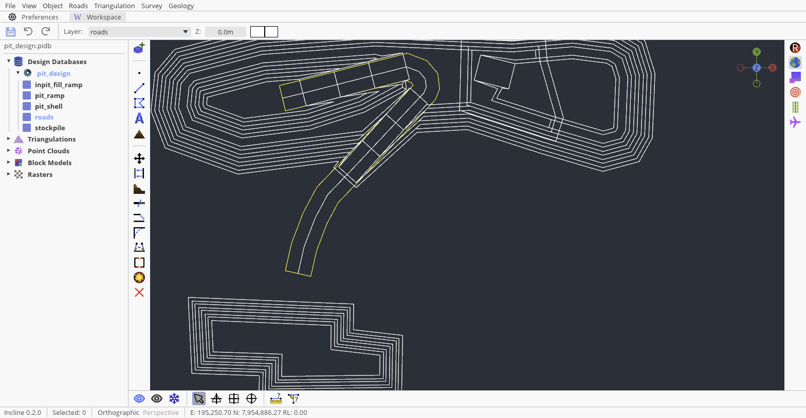
Open the PIDB that contains the pit strings and load the terrain or pit topology that will control the route. In the training workspace, pit_design keeps the bench, ramp, shell, road, and stockpile work in separate layers. Use the Explorer and Zoom to extents to confirm that the design and reference surface occupy the same coordinate area before adding anything.
This workflow assumes the pit strings have already been reviewed and a surface is loaded under Triangulations. A haul road should follow approved design criteria; this guide explains Incline’s controls, not site-specific dimensions.
Step 02
Make the road layer active and reduce clutter.
Create or load a layer named roads, haul_roads, or another project-specific name, then select it in the top toolbar’s Layer field. Road objects belong to the active layer just like points and polylines, so this check prevents a valid alignment from being stored among unrelated pit strings.
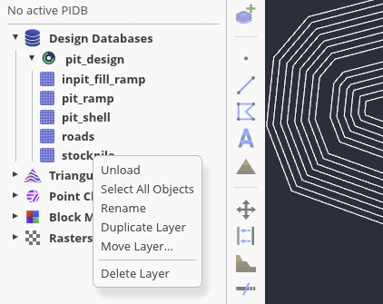
Right-click an irrelevant layer in the Explorer and choose Unload when it obscures the route. Unloading hides its objects and can reduce the geometry Incline draws; it does not delete the layer. Keep the crest, ramp tie-in, and any boundaries needed to judge clearance visible.
Step 03
Describe the road cross-section.
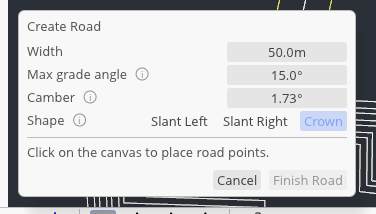
Select Create Road on the left toolbar. The docked panel asks for Width, Max grade angle, Camber, and Shape. Width is the complete edge-to-edge width about the centreline. Camber is entered in degrees, not percent, and controls the vertical cross-slope. Max grade angle limits the vertical slope of each centreline segment; Incline rejects a point when the new segment exceeds it.
Crown keeps the centreline high and drops both edges by the same amount. The drop on each side is half the width multiplied by the tangent of the camber angle. Slant Right is a continuous cross-fall toward the right: the left edge is high and the right edge low. Slant Left reverses that relationship. Choose the drainage direction intentionally, especially where the alignment changes direction; “right” and “left” are relative to the road centreline order.
Set these values before placing the first point and read the full-width preview, not only its centreline. A centreline may fit through a narrow corridor while one road edge crosses a crest or boundary. Changing width moves both preview edges around the same alignment, which makes this clearance check immediate.
The panel opens at 50 m width, 15° maximum grade, 1.73° camber, and Crown. Treat these as starting values only and replace them with the dimensions and limits approved for your design.
Step 04
Place the centreline on the surface.
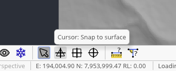
Choose Cursor: Snap to surface on the bottom toolbar. Start at a known tie-in and click along the intended centreline, adding points where the route changes direction or grade. Each accepted point receives its elevation from the visible triangulation beneath the cursor instead of the top toolbar’s working Z value.
Watch the live road edges as you move. They show the same resolved width and profile that the committed road will use. If the cursor has not found a valid surface snap, Incline does not place the point; move back over the loaded surface rather than continuing with an assumed elevation. Press Enter, right-click, or choose Finish Road after at least two points.
Step 05
Create a deliberate junction.
For a second branch, leave the road layer active, start Create Road again, and switch to Cursor: Snap to line for the tie-in point. Snap to the existing road rather than estimating the connection. The shared centreline point lets Incline resolve a connected T- or L-junction and preview the affected road edges together.
Continue with surface snapping after the connection if the branch must follow terrain. Read any viewport warning before committing: the road tool can reject a ramp that is too steep, a turn that is too sharp, a segment that is too short, or a turn that leaves insufficient junction clearance. Adjust point spacing or the alignment rather than forcing a bad preview.
Step 06
Read the complete design, then save.
Return to a plan view and inspect both edge lines through the ramp, switchbacks, and junction. Look for edge folds, abrupt drainage reversals, or a road that leaves the intended pit corridor. Compare the finished route with the pit strings and loaded surface, then use File → Save All or the floppy-disk button.
The route is on its own loaded layer, its centreline follows the intended elevations, and every connection is snapped rather than visually approximated.