
Step 01
Decide what the mesh should represent.
A triangulation is a separate 3D mesh, not a layer inside a PIDB. Use an open surface for terrain, pit floors, benches, and other sheet-like geometry that does not enclose a volume. Use Solid – fully closed only when the selected breaklines can form a watertight boundary around a volume. A solid is not simply a more complete-looking terrain surface; it has stricter input requirements.
Open the PIDB that owns the source polylines and confirm their elevations. You need a closed boundary, or connected open strings whose endpoints form one, before Incline can create a useful surface.
Step 02
Select the breaklines and triangulate.
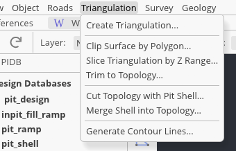
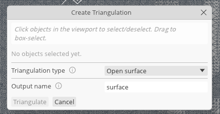
Open Triangulation → Create Triangulation…. Click eligible objects in the viewport to select or deselect them, or drag a box around a group. Incline lists the chosen strings in the dialog and highlights the geometry, making it easier to catch an unrelated boundary before processing.
Choose Open surface for the pit or terrain workflow, enter a distinct output name, and select Triangulate. The button remains unavailable until at least one object and a name are present. If nearby endpoints do not meet, correct the source first; use the offered Weld & Retry only when shifting contributing vertices by up to 5 cm is acceptable. The retry does not alter the source polylines.
When a closed solid fails, do not switch to Open surface merely to obtain an output. Check that its boundary can enclose a watertight volume and that the contributing breaklines represent more than one elevation. Use an open result only when a sheet is genuinely the intended model.
Step 03
Inspect triangles, not only shading.
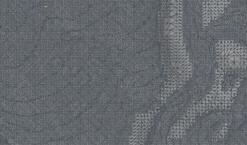
Open View → Enable Wireframes to reveal the edges of every visible topology. Orbit the view and inspect the boundary, tight corners, steep transitions, and areas between breaklines. Dense triangles are not automatically wrong, but unexpected bridges, missing faces, or edges crossing a void usually point back to incomplete or conflicting source geometry.
Turn wireframes off again when the overlay hides the design strings. Selecting a triangulation still gives it a highlighted wireframe, so the global option is best treated as an inspection mode rather than a permanent display requirement.
Step 04
Clip to a closed design boundary.
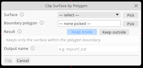
Create or identify a closed polygon with at least three boundary points, then choose Triangulation → Clip Surface by Polygon…. Select the loaded surface from the list or use Pick and click it in the viewport. Use the second Pick control to choose the closed boundary polygon.
Keep inside retains only the part of the surface within the polygon. Keep outside removes the part inside, leaving a polygon-shaped hole. Name the output before choosing Clip. The operation creates a new triangulation and leaves the source surface unchanged, so use a suffix such as _inside or _hole that states what was retained.
Confirm the Result choice and highlighted boundary before running the operation. “Keep” describes the output, and a plausible-looking plan view can still hide that the wrong side was retained.
Step 05
Generate contours into the active PIDB.
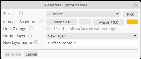
Choose Triangulation → Generate Contour Lines… and select the source surface. Set the minor interval for ordinary contours and the major interval for emphasized contours; the major value must be at least as large as the minor. The current starting values are 2 and 10, but interval choice should reflect the scale, vertical range, and purpose of the deliverable.
Enable Limit Z range when only a band of elevations matters. This can prevent thousands of irrelevant lines on a tall surface. Choose an existing layer in the active PIDB or leave New layer selected and enter a unique layer name. Contours are generated as editable polylines in that layer, not as another triangulation.
Step 06
Compare every derived result with its source.
Toggle visibility in the Explorer so the source and clipped surfaces can be checked independently. Zoom to the polygon boundary, enable wireframes briefly, and confirm that the cut follows the intended XY outline. Then unload the surface and inspect the contour layer for unexpected gaps, crowding, or an interval that is too fine to read.
Save the active PIDB so its contour layer is retained. Generated triangulations remain separate from that database and appear with an asterisk while unsaved. Right-click a generated entry and choose Save As…, or export it in the required triangulation format, when the mesh is part of the handover.
You have an inspected source mesh, a separately named clipped result, and contour polylines on an identifiable layer without overwriting the original inputs.