
Step 01
Build the selection you intend to change.
Return to Cursor: Regular and make sure no drawing tool is active. A normal click replaces the current selection. Hold Ctrl while clicking to add objects, or hold Shift to toggle an object in or out. Drag on the viewport to select many objects: a left-to-right box includes geometry that touches the box, while a right-to-left box requires geometry to be fully enclosed.
Work in a saved copy of a PIDB with at least two clearly named layers. Load only the layers needed for the edit and save once before beginning, so undo and the saved source both remain useful recovery points.
Check the Selected count in the status bar and inspect the highlighted geometry before issuing a batch command. For a whole layer, right-click its Explorer entry and choose Select All Objects; this is safer than drawing a large selection box across overlapping layers.
Step 02
Correct shape and appearance in Properties.
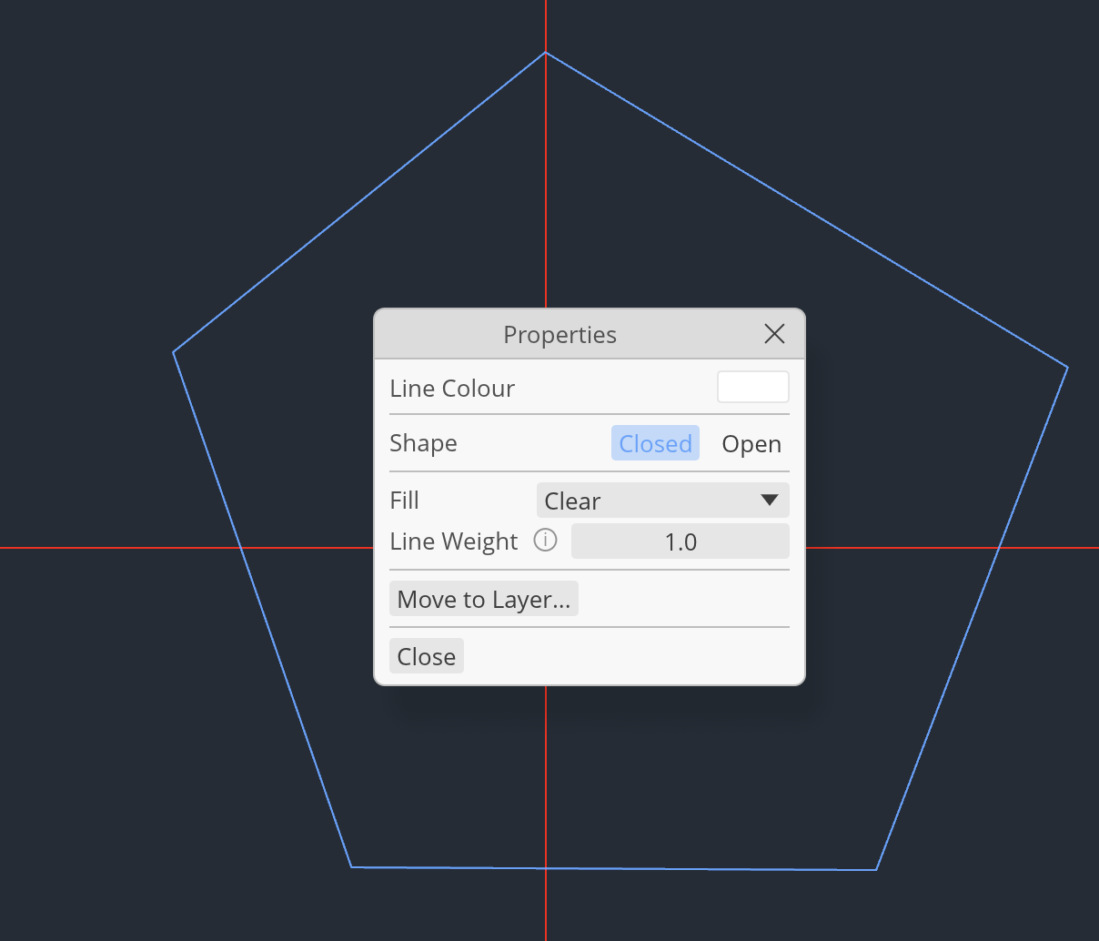
With one or more objects selected, quickly right-click one of them without dragging. The Properties panel opens beside the pointer. Change Line Colour for selected design objects. For selected polylines and polygons, set Shape to Open or Closed, choose a Clear, Crosses, Slashes, or Solid Fill, and enter a line weight from 0.1 to 20.0.
These controls apply immediately to the compatible objects in the current selection, so verify the selection before changing a shared value. Closing a string adds the last-to-first edge; it does not repair a crossed outline or reorder vertices. Use shape as a geometric decision, not just a styling switch. Press Ctrl+Z if a batch change affects more objects than intended.
Step 03
Move objects without redrawing them.
Use Move to Layer… at the bottom of Properties when correct geometry has been stored on the wrong layer. In the Move to Layer panel, choose Move to transfer the selected objects or Copy to retain the originals, then select the destination layer. Both actions preserve the object geometry and appearance; Copy creates separate objects that can be edited independently.
Copy is useful for a deliberate working version, but it can also produce coincident strings that look like a single object. Immediately unload the source layer or change the copy’s colour to prove that both sets exist. For routine organisation, prefer Move and reserve Copy for a named revision or a controlled alternative. Saving after a confirmed transfer gives the layer structure a clean checkpoint.
Step 04
Use Object commands for precise repairs.
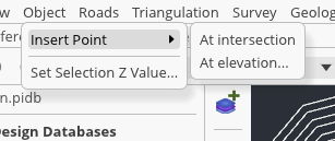
The top Object menu operates on selected design geometry. Insert Point → At intersection finds crossings in plan, using Easting and Northing rather than a shared 3D point. If two strings cross in plan at different RLs, both are processed and each new vertex receives the elevation interpolated along its own string. Insert Point → At elevation… asks for an RL and inserts vertices where selected polyline segments cross that elevation; segments already lying at the requested elevation are ignored. These commands add useful breakpoints without changing the path of the source string.
Set Selection Z Value… sets every point of the selected design objects to one Z value and updates the working Z field. It is appropriate for flattening a pad boundary or correcting a constant-RL string, but destructive for a ramp, road, or any line that must retain grade. Select only the intended objects, enter the value, review the object count in the dialog, and apply. Incline warns in the console when a command has no eligible selection.
Step 05
Manage the layer as a design unit.
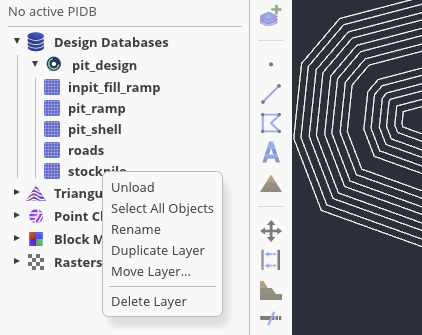
Right-click a layer in the Explorer to open its context menu. Load or Unload controls whether it participates in the working scene. Rename should be used early to replace vague names such as design with a purpose such as pit_crest_2026_07. Duplicate Layer creates a complete editable copy, which is a better revision boundary than copying a few objects when the whole design is changing.
Move Layer… transfers the entire layer to another PIDB that is already open. This is different from Move to Layer in Properties: one reorganises a layer between projects; the other reorganises selected objects inside the active project. Delete Layer removes the layer and its contents after confirmation, so unload it first and inspect the remaining design. On desktop, a dirty saved layer may also offer Discard Changes…; use that only when the last saved version is definitely the version you want.
Move Layer is a non-undoable cross-project transaction. It clears the complete undo and redo histories of both the source and destination PIDBs and leaves both projects with unsaved changes. Save or export both PIDBs immediately before the move, verify the destination afterward, then save both again.
Step 06
Review the design in context, then save.
Reload the reference layers and use Zoom to extents. Inspect joins between the pit strings and road, then orbit slightly to reveal accidental Z changes that a plan view can hide. Toggle edited layers one at a time: each should have a clear role, no unexplained duplicates, and no objects stranded on a temporary layer. If a line disappears behind a surface, use X-Ray Vision briefly rather than changing its colour or elevation just to make it visible.
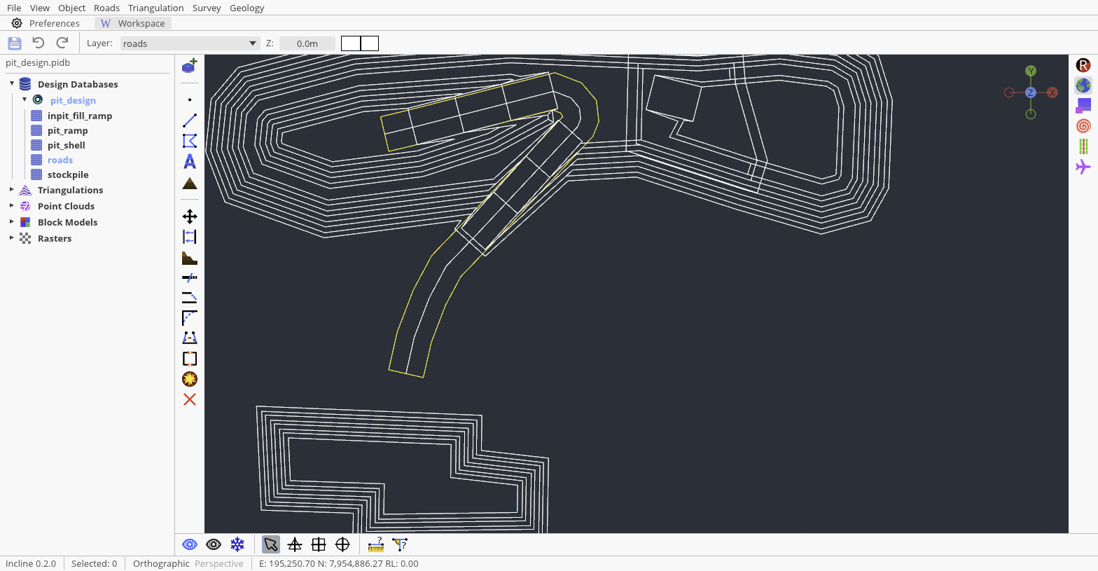
Choose File → Save All or the floppy-disk button. A disabled save control means no PIDB has unsaved changes. For a significant revision, export or reopen the design in a clean session and confirm that the expected layers load independently.
You can make a deliberate multi-object selection, edit compatible properties, repair elevations and intersections, move geometry at object or layer scale, and finish with a PIDB whose structure explains the design.