
Step 01
Create a PIDB.
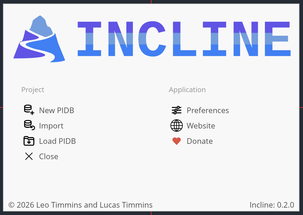
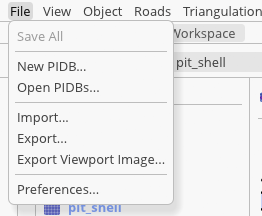
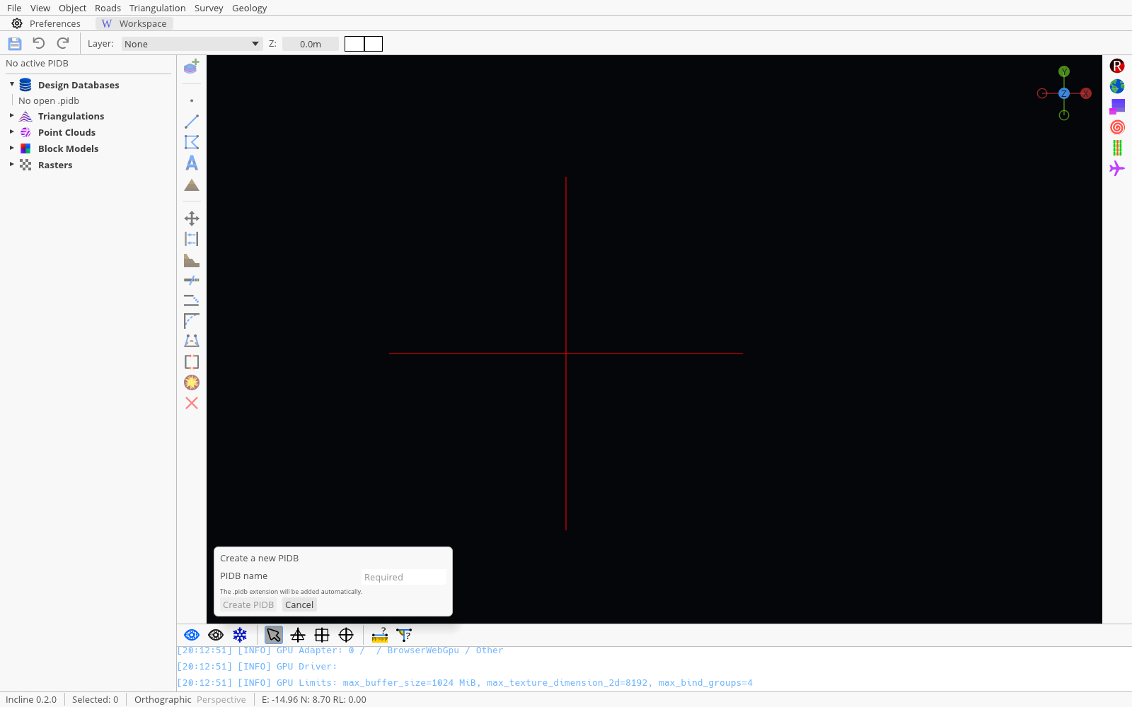
Open Incline and choose New PIDB on the welcome panel, or use File → New PIDB…. A PIDB is Incline’s editable project database: it groups layers and stores design objects such as points, polylines, polygons, text, and roads.
Enter a concise project name such as training_design. In Incline Web, PIDBs starts as an in-memory working project that will be destructed after closing the tab, so choose the floppy-disk button or File → Save All immediately after creating it. That first save writes the project to this browser’s IndexedDB storage rather than directly into a folder on your computer. You can press Download all PIDBs to save your work. This is not required on Incline Native as all progress is saved to your hard-drive
A closed polygon on a dedicated layer at a known Z elevation, with an explicit line colour and fill.
Step 02
Add a design layer.
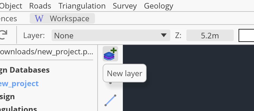
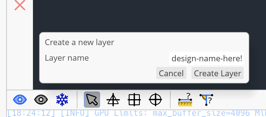
Select New layer at the top of the left toolbar. Enter a name that describes the geometry’s purpose, such as pit_floor, stockpile_toe, or no_dig_boundary, then choose Create Layer.
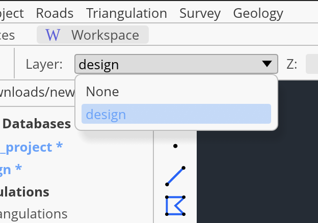
Open the Layer selector in the top toolbar and confirm the new layer is selected. Incline sends every new object to the active layer.
Step 03
Set the working elevation and appearance.
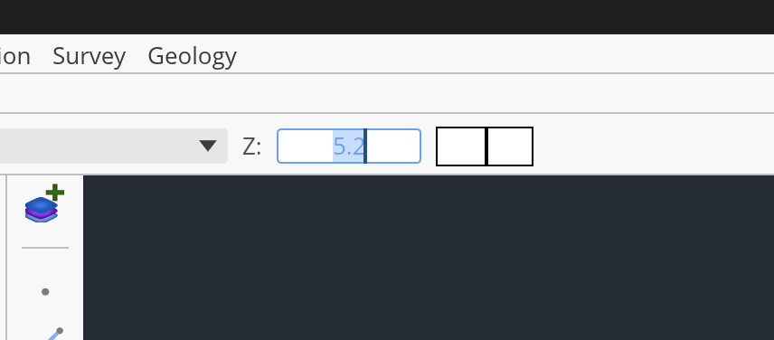
Enter the required elevation in the top toolbar’s Z field. For this exercise, lets set our working Z to 100.0 m. With the regular cursor mode active, every vertex you place uses this working elevation.
The colour and fill controls beside Z define the starting appearance for new geometry. Choose a line colour that contrasts with the dark viewport. A clear fill keeps underlying detail visible; a hatch or solid fill makes a closed boundary easier to recognise. These properties can be changed later.
The status bar reports the cursor’s Easting, Northing, and RL. If the design must attach to a topology rather than a fixed elevation, use Snap to surface/line/points; Guide 05 covers that workflow.
Step 04
Draw and close the polygon.
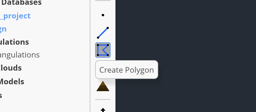
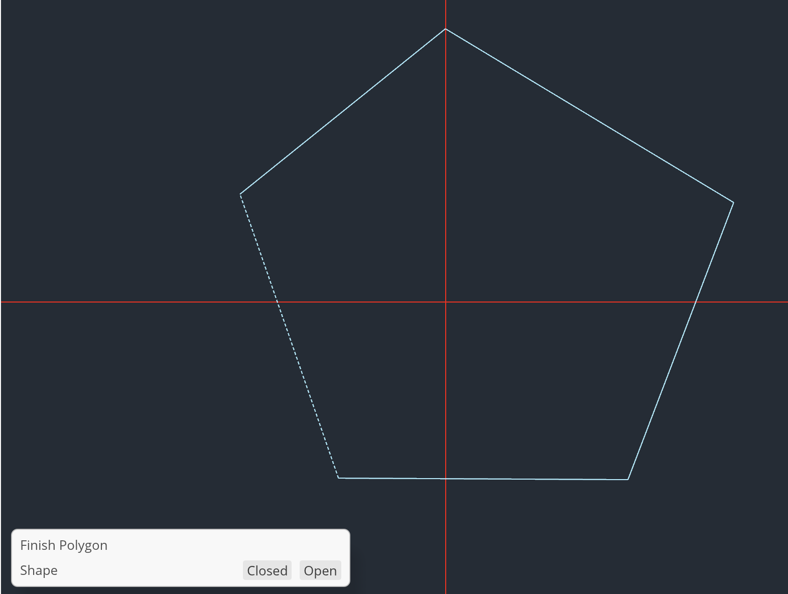
Select Create Polygon from the left toolbar. Click each vertex in order around the boundary. Keep the edges from crossing and use as few vertices as the shape needs; extra points make later editing harder without improving a simple design.
After the final useful vertex, press Enter. In the Finish Polygon panel, choose Closed and apply the result. Use Esc if you need to cancel the unfinished object and start again.
Step 05
Inspect and correct the result.
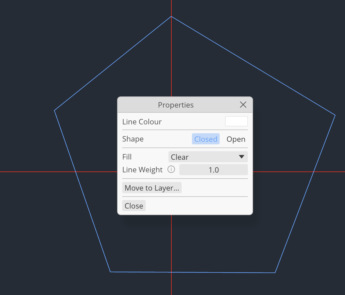
Right-click the polygon. You have opened the Properties dialog. Check that the object is closed, then play around with its line colour, fill style, and line weight.
If the shape is wrong, use the Move tool and select the points you want to move. You can move these points by dragging the arms of the movement gizmo. Press Enter to confirm the movement.
Step 06
Save, export, and verify.
Choose the floppy-disk button or File → Save All. The save control becomes disabled when the browser copy has no pending changes. On Incline Web, saving does not persist the current working state across a reload or later browser sessions, So you must use the Download All PIDBs button to keep a copy.
To save a backup of a PIDB, Open File → Export…, choose ProInspector database (.pidb), select your project, and export it.
You now have the complete your first Incline design: The next guide covers handling many projects and layers.
Next guideManage PIDBs and layers →