
Step 01
Prepare a small, unambiguous scene.
Load the PIDB layer that will receive the new geometry and, for surface work, load the required triangulation. Use the Explorer to unload unrelated layers or surfaces that overlap the work area. Snapping honours what is visible, so a tidy scene makes the intended target easier to acquire and the result easier to inspect.
You need an open PIDB with a loaded active layer. To practise surface snapping, also load a triangulation beneath the design area; to practise point or line snapping, keep suitable design geometry visible.
Select the destination in the top toolbar’s Layer field. Zoom close enough to distinguish individual strings, vertices, and surface features. The selected cursor mode will affect drawing and measurement tools, but it does not move existing objects simply by being enabled.
Step 02
Set the regular cursor’s working RL.
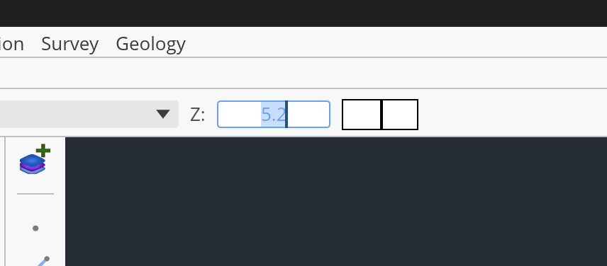
Enter the required value in the top toolbar’s Z field. The field is in metres and defines the horizontal plane used by the regular cursor. With Cursor: Regular selected, a point or polygon vertex is placed where the pointer ray meets that plane, making it the right mode for a constant-RL crest, toe, pad, or boundary.
Watch the status bar while moving across the viewport. Its E, N, and RL readout confirms the candidate coordinate before you click. If you need to borrow an existing object’s elevation, hover visible geometry and press the backquote key (`); Incline copies the picked Z into the Z field, rounded to four decimal places. Confirm the value rather than assuming the visually nearest line has the intended RL.
Step 03
Choose the target type, not just the nearest pixel.
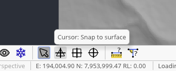
The four cursor buttons on the bottom toolbar are mutually exclusive. Regular uses the Z plane. Snap to surface ray-casts to the nearest visible loaded triangulation beneath the cursor. Snap to line targets polyline segments, resolved road centre lines, and triangulation edges. Snap to point targets point objects, design vertices, road vertices, and triangulation vertices.
Choose the narrowest mode that describes your intent. For example, use point snapping to join an exact endpoint rather than line snapping somewhere along its segment. When Incline has a valid target, a highlighted snap marker appears at the candidate location. In a snap mode, a drawing or measurement click is ignored until a target has been acquired; that safeguard prevents an unsnapped point from silently falling back to the working Z plane.
Step 04
Place and finish a snapped polygon.
Select Create Polygon from the left toolbar, then choose the required cursor mode. For a boundary draped over terrain, use surface snapping and move slowly enough to see the snap marker before each click. Every accepted vertex stores the target’s full E, N, and RL; the Z field does not flatten vertices obtained from a snap target.
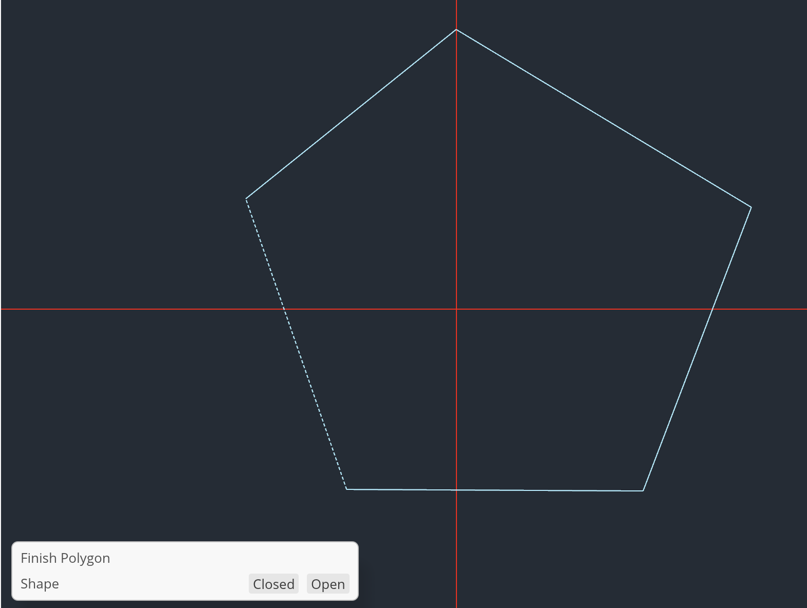
Place vertices in boundary order and avoid unnecessary points on straight runs. To finish, click the first vertex again for an immediate closed polygon, or press Enter and choose Closed in the Finish Polygon panel. Use Open only for a string that should not receive a closing segment. If the wrong target is acquired, press Escape to discard the in-progress stroke and correct the visible layers or snap mode before redrawing.
Step 05
Measure between controlled endpoints.
First select the cursor mode appropriate to the endpoints, then choose Measure distance, the ruler near the right end of the bottom toolbar. Click the first endpoint and move towards the second; Incline previews a measurement line between the first cross and the current cursor. Click the second valid target to lock the result.
The viewport label reports the straight-line three-dimensional distance in metres to three decimal places. This is not merely a plan distance: any RL difference contributes to the value. A third click begins a new measurement, replacing the earlier pair. Measurement is a temporary inspection tool and creates no PIDB object. It is unavailable while Flying Mode or Slice View is active, so return to the ordinary orthographic workspace first.
Step 06
Verify the geometry from more than one view.
Orbit to an oblique view and inspect the new polygon for sudden vertical jumps, doubled-back segments, or a vertex attached to the wrong surface. Return to plan with Reset view, then use point or line snapping to re-measure a representative edge. If surface snapping keeps choosing an upper surface, unload or hide that surface temporarily; only visible, unfrozen targets participate.
Finally, switch back to Cursor: Regular so the next task does not inherit an unintended snap requirement. Check the active layer, save the PIDB, and remember that the Z field may now contain a value copied with the backquote shortcut even though snapped vertices used their target elevations.
You can distinguish plane placement from geometric snapping, create a polygon whose vertices use deliberate XYZ targets, and validate its true spatial distance without adding measurement objects to the project.